GPS module
● GPS module overview
GPS module definition
The GPS module meaning a signal receiver, which can use wireless or limited connection to transmit the signal to the cloud server for processing to achieve precise positioning.
GPS module description
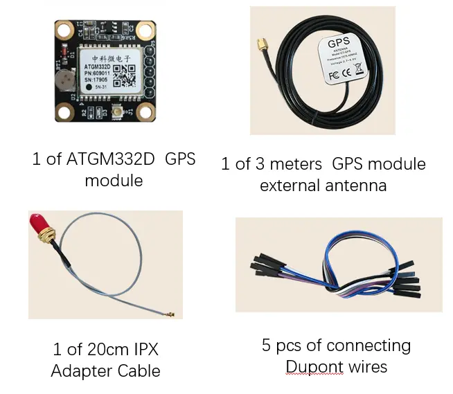
The GPS module kit is a high-performance, low-power GPS, Beidou dual-mode GPS module kit. It adopts the ATGM332D-5N-31 module scheme of Zhongke Microelectronics Company, which can output GPS and Beidou positioning information to the microcontroller system and computer through the serial port, which is simple and convenient to use.

● GPS module datasheet
| Characteristic | GPS module description |
|---|---|
| Basic functions(GPS module uses) | 3D position positioning (latitude and longitude, altitude) Speed measurement Time service |
| Navigation System | GPS, Beidou BDS (dual mode) Assisted GNSS support |
| GPS module accuracy of Positioning | 2.5 meters (circular probability error CEP50) |
| GPS module accuracy of Speed measurement | <0.1m /s |
| GPS module accuracy of Heading angle | 0.5 degrees |
| GPS module accuracy of Timing | < 30ns |
| Number of RF Channels | Support full constellation Beidou BDS, GPS simultaneous reception |
| Positioning time | Cold start: ≤32s, capture sensitivity -148dBm. Hot start: ≤1s, capture sensitivity -156dBm. Recapture: ≤1s, capture sensitivity -160dBm. |
| Cold Start Capture Sensitivity | -148dBm |
| GPS module communication protocol | Bluetooth 2.0. With EDR, 2Mbps-3Mbps modulation degree |
| Hot Start Capture Sensitivity | -156dBm |
| Recapture sensitivity | -160dBm |
| Tracking sensitivity | -162dBm |
| Navigation information maximum update rate | 1Hz (default), max 10Hz |
| Serial port | Reserved serial ports with TTL level standard, support and use 3.3/5V level standard. Supported transfer rates: 4800, 9600, 115200bps, the default is 9600bps. |
| GPS module communication protocol | NMEA0183 |
| The output latitude and longitude coordinate system | wGs-84 coordinate system |
| Maximum height | 18000m |
| Maximum speed | 515m/s |
| Maximum acceleration | 4g |
| Power supply | Power supply through the power supply pin 3.3~5V drawn by the module. Rechargeable battery to power backup domain after mains power loss. |
| Operating temperature | -40 to +125 degrees Celsius |
| GPS module power consumption | Continuous operation <25mA (@3.3V) |
● GPS module configuration for hardware
The GPS module has stable performance, beautiful device interface layout and easy to use. Its resource description is as shown in the figure:
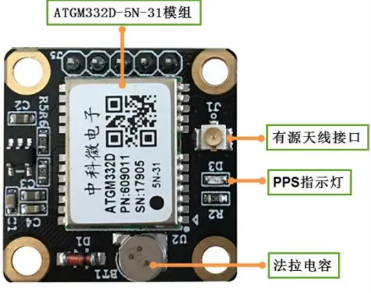
| No. | Name | GPS module description |
|---|---|---|
| 1 | ATGM332D-5N-31 module | With fast star search capability (32S) and accurate positioning effect, it is very suitable for applications with high performance and low power consumption. |
| 2 | XH414 Farad electricity | XH414 Farad capacitor, the parameters are: 3.3V 0.07F. Its function is the same as that of a lithium battery. When the main power is turned off, it can supply power to the RTC part of the GPS module kit, so that the GPS module kit can quickly search for satellites when it is started next time. Generally, it can last for 1 hour. |
| 3 | Active Antenna IPX Interface | The IPX interface is used to connect active antennas to enhance the signal. |
| 4 | PPS indicator | After the module is powered on, the time pulse indicator will be on. After the GPS module kit receives the time information, the time pulse signal indicator will flash at a frequency of 1Hz by default, and the signal frequency can be adjusted. |
● GPS module external antenna
Active antenna: This GPS module needs to be connected to the antenna when using it, and good satellite signals can be received by using the matching active antenna.
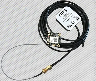
3m antenna for free
● GPS module specifications for Active Antenna
| GPS active antenna | Specification | |
|---|---|---|
| Ceramics | Center frequency | 1575士1MHz |
| Bandwidth | CF±8MHz | |
| Polarity | RHCP | |
| Gain | 5dB(Zenith) | |
| V.S.W.R | < 1.5 | |
| Impedance | 50Q | |
| Axial Ratio | 3dB(max) | |
| Dimension | 25*25*4mm | |
| Amplifier | Gain | 28士2dB |
| Noise Figure | <1.0 | |
| Filter Insertion Loss | < 3dB | |
| Ex-band Attenuation | 35dB@CF±50MHz/50dB@CF±100MHz | |
| Supply voltage | 2.7-5V DC | |
| Current Consumption | 16mA | |
| V.S.W.R | < 2.0 | |
| Mechanical | Wire | RG174 96 braided copper spray tin |
| Connector form | SMA | |
| Radome Material | PC | |
| Mounting Method | Magnet/Adhesive | Working environment | Operating temperature | -40℃~ +85℃ |
| Relative Humidity | Up to 95% | |
| Waterproof level | IP65~IP67 | |
| Vibration | 10 to 55Hz with 1.5mm amplitude 2hours | |
| Environmentally Friendly | ROHS environmental protection | |
● GPS module experiment
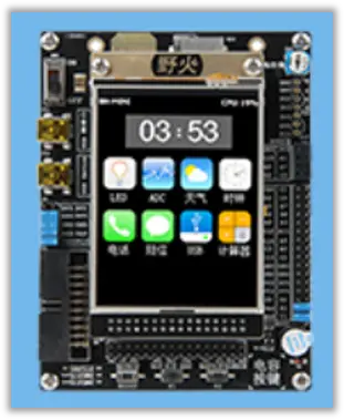
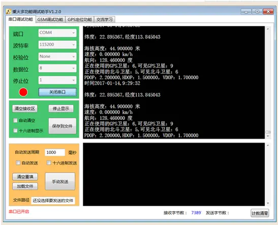
1.GPS_Decode_SDCard experiment (decoding results output by the experimental serial port debugging assistant) This program decodes the GPSlog.txt file of the SD card on the development board (please make sure that the file is in the card). During the experiment, connect the USB cable to the USB TOUART interface of the development board to receive the decoding information of the GPS log from the development board. See Figure, the serial port debugging assistant shows the received decoding information.
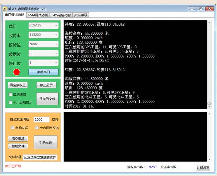
2.GPS_Decode_USART experiment (experimental serial port debugging assistant prompt information).
This program needs to connect the GPS module kit to the corresponding serial port pins of the development board. When the satellite signal is good, the serial port debugging assistant will display the real-time positioning information decoded by STM32 development board, as shown in the figure.
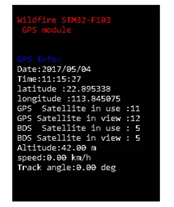
3.Experimental screenshots
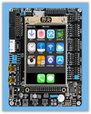
This procedure is the same as above, the GPS module needs to be connected to the development board. When the GPS signal is good, the serial port debugging assistant and the onboard LCD screen will display the real-time positioning information, as shown in the figure.
● GPS module Frequently Asked Questions
1.Why is there a large deviation when inputting the decoded latitude and longitude data into the map?
Answer: This is because of the different coordinate systems. The domestic electronic map adopts the "Mars coordinate system", and the output of the GPS module is the standard WGS-84 coordinate system. This is not because the positioning of GPS module kit is not accurate.
2. Why can't I see the original data when using the PC to test?
Answer: Please check the connection between the GPS module and the USB-to-serial TTL cable, pay special attention to the cross-connection between the serial cable and the TXD and RXD of the GPS module (ie TXD<-->RXD, RXD<-->TXD). In addition, confirm that the COM port opened by the host computer corresponds to the USB to TTL line, and that the baud rate is required to be 9600.
3. When using the computer host computer to test, there is original data, but after a long time, the positioning has not been successful?
Answer: Confirm that the GPS module external antenna is well connected, and confirm the connection of the GPS module external antenna according to the GPTXT statement in the description; confirm that the antenna is in a position with good satellite signal, the antenna needs to be facing up, and placed outside (a window sill or balcony) without obstruction thing. If the antenna is placed indoors, it cannot be positioned, and the satellite signal basically has no signal indoors (the mobile phone can be positioned indoors because it also uses mobile and Wi-Fi network assistance, and it cannot be positioned purely using satellite signals)
4. Why is there no decoding information output when running the STM32 development board to decode the SD card log file program?
Answer: Make sure that the debugging assistant opens the COM port for debugging the STM32 development board kit and the baud rate is 115200, confirm that the development board has been connected to the SD card, and the root directory of the SD card has the GPSlog.txt log file under the project path.
5. When running the decoding program of the STM32 development board kit, why is there no decoding information output? (The serial port program does not update the decoding data, and the LCD screen is always on the initial interface.
Answer: Make sure that the debugging assistant opens the COM slogan for debugging the STM32 development board and the baud rate is 115200. Check the hardware connection between the module and the development board corresponding to STM32 development board kit. For the STM32F103 microcontroller development board STM32F103ZET6 and STM32F407 discovery board (STM32F407ZGT6) , pay attention to the problem of jumping caps.
6. When running the STM32 development board kit decoding program, why is the location not marked on the host computer map?
Answer: To use the function of marking the location on the host computer, please directly use the USB to serial TTL cable to connect the location GPS module to the computer. The STM32 development board kit decoding program only sends the decoding results to the computer without marking.
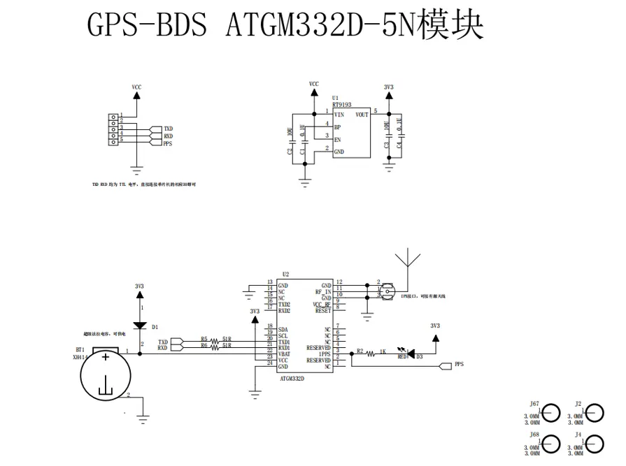
● GPS module schematic
● GPS module Shipping List
● Contact us
We are a professional GPS module manufacturers, with a variety GPS module typesto choose from. If you want to buy a positioning module, or you want to know the GPS module price , GPS module cost, the GPS module specs and other information, please click WHATSAPP to contact us.


