Breadboard
Breadboard is a circuit board specially designed and manufactured for solderless experiments of electronic circuits, that is, an integrated circuit experiment board, which is a kind of plug-in board. Breadboard is named breadboard because there are many small jacks on the board, much like the holes in bread. The breadboard is very suitable for the assembly and debugging of electronic circuits.
● Our breadboard series products
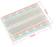
| Breadboard name | 400 holes breadboard |
|---|---|
| Specifications | 400 holes |
| Breadboard size | 8.5*5.5cm |
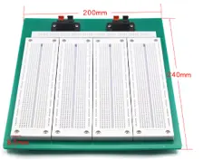
| Breadboard name | SYB-500 breadboard |
|---|---|
| Specifications | SYB-500 |
| Breadboard size | 240*200*8.5mm |
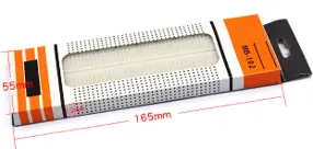
| Breadboard name | MB-102 breadboard |
|---|---|
| Specifications | MB-102 |
| Breadboard size | 165*55*10mm |
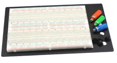
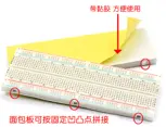
| Breadboard name | 1660 holes breadboard |
|---|---|
| Specifications | 1660 holes |
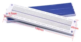
| Breadboard name | 830 holes breadboard |
|---|---|
| Specifications | 830 holes |
| Breadboard size | 188*46*8.5mm |
| Breadboard name | SYB-130 breadboard |
|---|---|
| Specifications | SYB-130 |
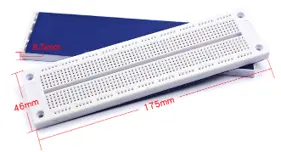
| Breadboard name | SYB-120 breadboard |
|---|---|
| Specifications | SYB-120 |
| Breadboard size | 175*46*8.5mm |
● Breadboard introduction
1)Breadboard definition
The breadboard is a circuit board specially designed and manufactured for solderless experiments of electronic circuits, that is, an integrated circuit experiment board, which is a kind of plug-in board.
The breadboard kit is called a breadboard because there are many small jacks on the board, much like the holes in bread. There are several small sockets (holes) on this "board".
2)Breadboard usage
When conducting circuit experiments, the pins and wires of electronic components can be inserted into the corresponding holes according to the circuit connection requirements, so as to make contact with the elastic contact springs in the holes. , which are connected into the required experimental circuit.
3)breadboard uses and functions
Breadboards are great for assembly and debugging of electronic circuits.
● Breadboard characteristics
1. Recyclable and environmentally friendly recycling.
2. The color of the structure is clear, no welding is required, and the installation and disassembly are very convenient.
3. Easy to use and easy to learn.
4. Durable and quality guaranteed.
5. Affordable prices to meet the needs of many customers.
● Breadboard types
Breadboards are generally divided into solderless breadboards, single breadboards, and combination breadboards.
Solderless breadboard is a board that does not have a motherboard as a base, and does not have a soldered power socket, but can expand a single breadboard.
Connect the two poles of the power supply to the jacks on both sides of the breadboard kit, and then you can plug in the components for breadboard circuit testing experiment (the power supply must be disconnected during the process of inserting components), and then turn on the power supply for use. When there are more than 5 components or a group of jacks cannot be inserted, you need to use breadboard wire to connect multiple groups of jacks.
The advantage of a solderless breadboard is that it is small in size and easy to carry, but the breadboard disadvantages is that it is relatively simple, the breadboard power connection is inconvenient, and the area is small. Large-scale breadboard circuit testing experiments are not suitable. To use it for large-scale breadboard circuit testing experiments, should use screws to fasten multiple breadboards to a large board and connect them with breadboard wires.
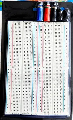
Single breadboard is a breadboard kit with a motherboard as the base, and a special terminal for the power supply, and even some breadboards that can perform high-voltage experiments with ground terminals.
This kind of breadboard is more convenient to use, that is, the power supply is directly connected to the binding post, and then the components are inserted for experiments (the power supply must be disconnected during the process of inserting the components). When there are more than 5 components or a group of jacks cannot be inserted, you need to use breadboard wire to connect multiple groups of jacks.
The advantage of a single breadboard is that it is small in breadboard size, easy to carry, and can easily turn on and off the power supply, but the breadboard disadvantages are that it has a small area and is not suitable for large-scale breadboard circuit testing experiments.

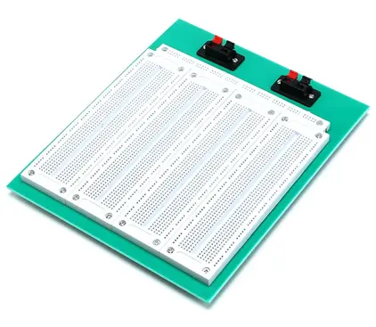
Combination breadboard is a board that combines many solderless breadboards together. Generally, 2-4 solderless breadboards are fixed on the motherboard, and then the power lines of each board are connected together with the copper foil in the motherboard. The professional combination breadboard is also designed with sub-power control for different circuit units, so that each board can carry different breadboard voltage according to user needs. Combination breadboards are used in the same way as single breadboards. The advantage of the combination breadboard is that it can easily turn on and off the power supply, has a large area, can conduct large-scale breadboard circuit testing, and has high mobility and a wide range of breadboard uses. The breadboard disadvantages is that it is bulky and heavy, so it is not suitable for carrying, and is suitable for laboratories and electronics enthusiasts.
● Breadboard explained on structure
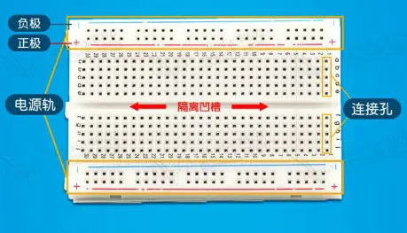
1. Structural features of the breadboard: The whole breadboard is made of thermosetting phenolic resin, and there are metal strips at the bottom of the board. Holes are drilled at the corresponding positions on the board so that the components can be in contact with the metal strips when they are inserted into the holes, so as to achieve the purpose of conduction.
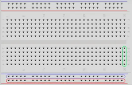
Generally, every 5 orifice plates are connected with a metal strip. There is generally a groove in the center of the breadboard, which is designed for the need for integrated circuit and chip tests.
2. There are two columns of jacks on the upper and lower sides of the breadboard (marked as power rails in the figure below), which are generally used as the path for the introduction of breadboard power.
The column marked with "+" has 5 groups of jacks, 5 in each group (the inner 5 holes are connected), all of which are positive. The column marked with "-" also has 5 groups of jacks, each group of 5 (the internal 5 holes are connected), all of which are grounded. If you want to use the whole breadboard kit, usually "+" and "+" are connected with breadboard wires, and "-" and "-" are connected with breadboard wires too.
The connection hole is divided into upper and lower parts, which are used to insert the original and jumper. The 5 jacks (i.e. a-b-c-d-e, f-g-h-i-j) in the same column are connected to each other; the column and column (i.e. 1-30) and the upper and lower parts of the groove (i.e. e-f) are not connected.
● How to use breadboard
How breadboard works
The breadboard is divided into two separate parts.
The first part, the two rows separated by red and blue wires on the left and right sides, are used to connect power (red) or ground (blue), and the jacks of each row are connected together internally. Generally used to connect the positive and negative poles of the power supply.
In the second part, the middle 10 rows of jacks are divided into left 5 and right 5 (a, b, c, d, e) for identification, and these 5 jacks are linked together. The electronic components in the circuit are generally connected to it, and then connected to the power supply and GDN next to it.
How to use a breadboard
Without soldering and manual wiring, the circuit and components can be tested by inserting the components into the holes, which is convenient to use.
There are several metal jacks connected to the conductive metal strips on the reverse side of the breadboard, which correspond to the holes on the front, so you need to pay attention when using the breadboard. When inserting the integrated block into the breadboard, it is often easy to cause loosening. At this time, the two rows of breadboard pin of the integrated block can be pressed closer to each other so that they can be firmly inserted into the small holes.
In addition, the test point and ground terminal in the circuit should be specially drawn out for measurement, otherwise the probe of the instrument is directly connected to the component foot, which will easily cause the component to be pulled loose.
● Precautions for the breadboard uses
The diameter of the copper core of the pin or wire inserted into the hole on the breadboard is 0.4-0.6mm, which is slightly smaller than the diameter of the pin.
The component pins or wire heads should be inserted into the square holes in the vertical direction of the breadboard, and a slight and uniform frictional resistance should be felt. When the breadboard is upside down, the components should be clamped by the reeds without falling off.
The breadboard should be stored in a ventilated and dry place, especially to avoid being corroded by the electrolyte leaked from the battery.
To keep the breadboard clean, do not plug soldered components on the breadboard.
Application of breadboard
The breadboard is a tool for making circuit experiments, and various electronic components can be inserted or removed on the breadboard kit as needed. The breadboard not only eliminates the cumbersome soldering of electronic components on the circuit board and saves the assembly time of the circuit, but also the electronic components can be reused on the breadboard, saving costs. Breadboards are great for assembling, debugging, and practicing all kinds of electronic circuits. Breadboards are also very suitable for electronic engineers, beginners of electronic circuits, and electronic hobbyists for product development.

● Breadboard case - Experiment
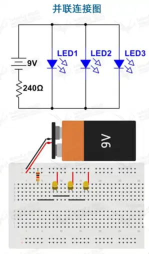
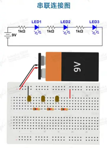
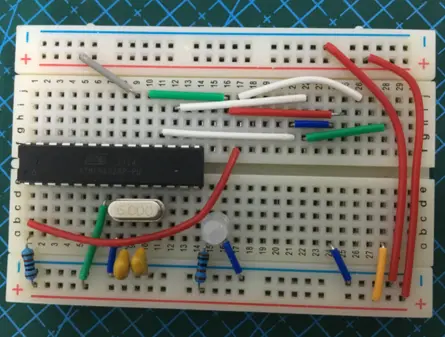
The following figure is the breadboard circuit diagram and breadboard connections diagram of lighting the LED lamp as breadboard circuit examples
