STM32 development board (STM32F767IGT6)
● STM32F103 development board (STM32F103RCT6) introduction
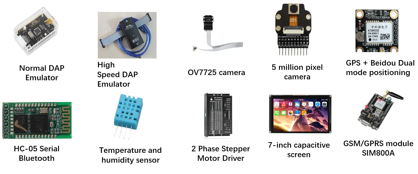
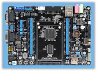
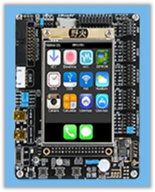
The STM32 development board (STM32F767IGT6) also known as STM32F767IGT6 development board, it is a circuit board that uses the STM32F767IGT6 as the main control chip, it is mainly used to develop the software and hardware of the STM32F767IGT6 microcontroller. The STM32F767IGT6 development board uses a 32-bit high-performance ARM Cortex-M7 core processor, this processor uses a 6-stage pipeline and has a performance of up to 5 CoreMark/MHz, far exceeding the previous highest performance STM32F4 (Cortex M4 core) series. This STM32 development board kit adopts a new baseboard + core board design, which not only has the functions of the smallest system, but also the core board can be used separately from the baseboard, which is small and flexible. The STM32F767IGT6 core board is rich in embedded resources, including CPU (operating frequency up to 216MHZ), pins (176 of STM32 development board pinout), PLASH, keys, reset keys, stm32 development board LCD interface, USB interface and other resources, with strong performance. The baseboard integrates WIFI, Ethernet, MP3, recording, 232, 485, buzzer, USB and USB-HOST, serial port, 6-axis gyroscope, photosensitive sensor and many other modules. The STM32F767IGT6 development board not only integrates rich on-board resources, but also can lead out some IO ports for users to connect modules, which is very suitable for promoters, engineers, and technicians to learn and develop.
● STM32 development board (STM32F767IGT6) features
1.Flexible design
This stm32 development board kit adopts a new design of the base board + core board, and one board is multi-purpose. The base board is compatible with F429, F767, H743 core boards, with high performance ratio, and 3 core boards can be switched for use. The core board can also be used alone, with on-board RGB stm32 development board screen screen interface, USB power supply port, stm32 development board lcd, buttons, SDRAM, NAND (only in V2 version) and other resources.
2. Powerful performance
The STM32 development board (STM32F767IGT6) uses the STM32F767IGT6 as the main control chip, which uses a high-performance Cortex™-M7 core processor with an operating frequency of 216MHZ. The chip has a high-performance single/double-precision floating-point arithmetic unit, supports single/double-precision data processing instructions and data types, and also has a complete set of DSP instructions and a memory protection unit (MPU) to improve application security, so STM32F767IGT6 Chip performance and computing have been greatly improved, making the development board more powerful.
3. Rich onboard resources, many peripheral interfaces and powerful functions
The STM32 development board (STM32F767IGT6) is a development board with wifi, also a development board with ethernet, and is a development board with can bus, it has on-board WIFI, Ethernet, MP3, CAN, 485, 232 and many other microcontroller development board module to achieve specific functions.
The development board stm32f767 supports the following functions:
1.Support Gigabit LAN/Dual RS232 serial port/RS485/CAN/USB Host;
2.Support audio and video playback, soft solution WAV/MP3/FLAC/APE/AVI and other audio and video formats;
3.Support 2.8/3.5/4.3/7 inch MCU screen/RGB screen, support resistive/capacitive touch;
4.Support hardware JPEG decoding, support double-precision floating-point operations;
5.Support six-axis sensor (MPU9250), DMP attitude calculation;
6.Support NES & SMS games (full speed, with audio), powerful performance;
7.Support NAND FLASH, with bad block management/wear leveling/ECC check;
8.Support two-dimensional code (and barcode) recognition/face recognition (need to purchase OV5640 module), handwriting recognition/pinyin input method, call/send and send text messages.
● STM32 development board (STM32F767IGT6) version
There are 2 versions of the STM32 development board (STM32F767IGT6) :
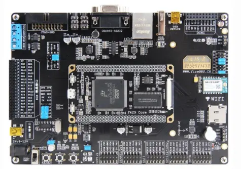
STM32F767IGT6 development board –V1
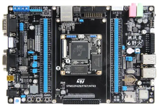
STM32F767IGT6 development board – V2
● STM32 development board (STM32F767IGT6) version
| Function | V1 version | V2 version |
|---|---|---|
| Reset key | restart function | |
| Function key K1K2 | Can be used for parameter adjustment control, etc. | |
| CAN | Can realize CAN communication and Modbus protocol, etc. | |
| LCD interface RGB888 | LCD screen interface, used to display the screen | |
| USB to Serial | Can realize card reader, virtual serial port and other functions | |
| Full color LED light | Realize the running water lamp experiment | |
| TF card holder | It can be used to store large files, such as MP3, video, pictures, etc. | |
| RTC battery holder | Put the button battery, STM32 backup power supply, maintain the storage of data in the backup area, and the operation of the RTC clock chip. | |
| BOOT jumping | change the circuit | |
| MP3 WM8978 | Music player | |
| Ethernet | Connect the network cable, which can be used for Ethernet communication, TCP/IP protocol and other functions. | |
| Potentiometer | Collect voltage and convert analog signal to digital signal | |
| Camera interface | Can realize photography, video monitoring, etc. | |
| USB HOST | Connect other USB slave devices such as U disk/USB mouse/USB keyboard to realize USB host function. | |
| LVDS interface | None | transmit data, send and receive signals |
| Speaker interface | External speaker | |
| LCD backlight interface | LCD backlight function | |
| Module interface | Input and output expansion interface | |
| Acrylic protection board | Excellent weather resistance, good process ability, strong impact resistance, insulation, long life, easy to clean, recyclable. | |
| WIFI | Model: EMW1062, realize wireless network | Model: AP6181, realize wireless network |
| Infrared interface | There is an interface and an external module to realize the infrared remote control function. Through this receiver, it can accept the infrared signals of various remote controls that are common in the market. | The infrared receiver is directly welded on the base board. |
| light sensor | Analog input | ALS+PS+1RLED digital input |
| USB Device | Mini USB | Micro USB |
| MAX232 | 1 | 2, the level conversion chip is SP3232, and 2 DB9 interfaces are expanded externally, one female and one male, which can be used for slave communication and host communication |
| EEPROM | On the base board, the AT24C02 chip has a storage capacity of 256 bytes, which can store important data, such as passwords, touch screen calibration coefficients, etc. | On the core board, the AT24C02 chip has a storage capacity of 256 bytes, which can store important data, such as passwords, touch screen calibration coefficients, etc. |
| Download interface | JTAG is on the backplane and SWD is on the core board for code download and emulation debugging. | JTAG and SWD are on the base board for code download and emulation debugging. |
| Switch | Toggle Switches | Key lock switch |
| Lead out IO | Lead out a few bus IO | Lead out all available IO |
● STM32 development board comparison STM32F767IGT6 V1 and V2 on core board hardware resources
| Function | V1 version | V2 version |
|---|---|---|
| Main chip STM32F767IGT6 | 32-bit high-performance ARM CORTEX-M7 processor, up to 216MHZ frequency, built-in instruction and data Cache, integrated JPGE codec, double-precision hardware floating point computing unit (DPFPU) and DSP instructions, built-in RGB LCD interface, 1024KBFLASH ,512KB SRAM storage capacity, etc. | |
| Reset key | restart function | |
| SWD debug interface | Can be used for program next week, online simulation debugging, etc. | |
| LCD-RGB888 interface | Can be used for liquid crystal display project development, such as human-machine touch screen, advertising machine, etc. | |
| Serial USART1 interface | The serial port drawn from the core board can be used for serial communication. | |
| Micro USB interface | Compatible with Android phone data cable, this interface can be used as USB SLAVE or as USB HOST (OTG). When used as HOST, an external USB OTG cable is required. At the same time, this interface is also the main power supply port for the core board (when the core board is used alone). | |
| Function key | 1 | 2 |
| NAND FLASH | None | The NAND FLASH chip (U4) expanded outside the core board, the model is: MT29F4G08, the capacity is 512M bytes, which can be used to store fonts, pictures, music, video files, etc. |
| SDRAM | 8M | This is the SDRAM chip (U3) expanded outside the core board, the model is: W9825G6KH, the capacity is 32M bytes, it can cope with various large memory demand scenarios, such as GUI design, algorithm design, big data processing, etc. |
| SPI FLASH | 16M | The SPI FLASH chip (U6) expanded outside the core board, the model is: W25Q256, the capacity is 256Mbit, that is, 32M bytes, which can be used to store fonts and other user data to meet the requirements of large-capacity data storage. |
| EEPROM | On the base board | On the core board, the model is: 24C02, and the capacity is 2Kb, which is 256 bytes. It is used to store some important data that cannot be lost when power off, such as some parameters set by the system/touch screen calibration data, etc. With this, you can easily realize the power-down data storage. |
● STM32 development board (STM32F767IGT6) -V1 Core board hardware configuration list
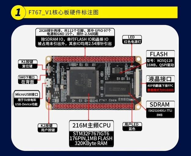
| Model | STM32 development board (STM32F767IGT6) -V1 Core board |
|---|---|
| Size | 84.4*47.5MM |
| PCB | 6 layers, black immersion gold |
| CPU | STM32F767IGT6, 176PIN, 1MB FLASH, 256KByte RAM |
| Main frequency | 216M |
| Serial FLASH | 16MB, model: W25Q128, can be used to store fonts and other user data |
| SDRAM | 8MB, model: IS42S16400J-7TLI, for data processing |
| Download | 1 of SWD download port for code download and emulation debugging |
| Key | 1 reset key, 1 user key |
| Micro USB port | 1 for 5V power supply and USB-Device function |
| LDO chip | 1, voltage conversion chip, realize 5V to 3.3V |
| Download | 1 of SWD download port for code download and emulation debugging |
| LCD interface | 1, using a 40P flip under the FPC, 0.5MM spacing, the data format is RGB888 |
| LED | 1 power LED, 1 user LED |
| GPIO | Except for SDRAM IO, serial FLASH IO and crystal oscillator IO, which are occupied and not led out, other IOs are led out by 2.54 pin headers. |
● STM32 development board (STM32F767IGT6) -V1 Baseboard hardware configuration checklist
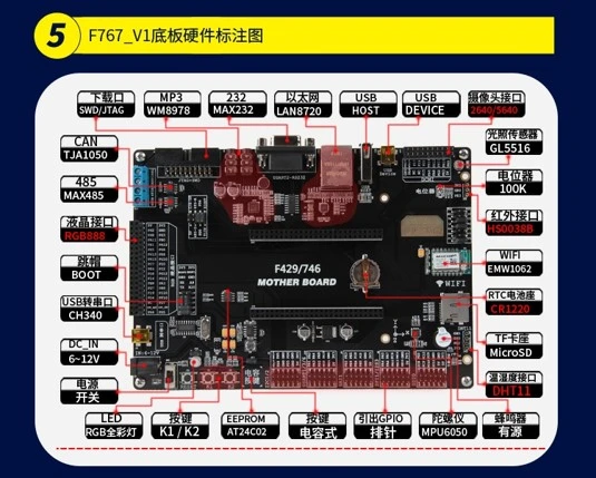
| Model | STM32F429_F767_H743 baseboard (F4/F7/H7 shared baseboard) |
|---|---|
| Size | 177.8*126.4MM |
| PCB | 2 layers, black gold immersion gold |
| Core board interface | Connect to the core board, compatible with F429 and F767 and H743 core boards |
| WIFI | Model: EMW1062, SDIO bus interface, the maximum speed can reach 2MB/S, realize wireless network function |
| Ethernet | Can be connected to HCO5 Bluetooth module |
| EEPROM | Model: AT24C02, capacity 256 bytes, AT24C02 chip, 256B capacity, used to store some important data that cannot be lost when power off, such as some parameters set by the system/touch screen calibration data, etc. Such as computer files, passwords, touch screen calibration coefficients, etc. |
| SD card | TF card within 32GB can be expanded externally for storage of large files, such as MP3, video, pictures, etc. |
| RTC transposon | 1 CR1220 battery holder, put button battery, the power supply interface of STM32 backup area, can be used to provide energy to the backup area of STM32, maintain the storage of data in the backup area and the operation of the RTC clock chip when the external power supply is cut off. |
| Power Input | Support DC 12v, USB 5V input |
| Power Output | LDO: AMS1086-3.3, can output 3.3V |
| MP3 | Model: WM8978, support playback and recording |
| Buzzer | 1 active buzzer, which can realize functions such as alarm prompt, music box, etc. |
| Potentiometer | 1 of 100K precision patch potentiometer can collect the analog voltage of the potentiometer, the WM+RC filter circuit expands the DAO to output the analog signal, and the ADC can collect such as smoke/harmful gas concentration detection |
| Key | 1 reset key, 2 ordinary keys, and 1 capacitive key, which can be used for parameter adjustment and control, among which RST is the reset function |
| LED | 1 RGB LED, 1 Power LED |
| Liquid crystal | External 5"/7" RGB LCD module |
| STM32 LTDC driver, LCD stm32 development board screen does not need its own driver chip | |
| Accelerometer | Model: MPU6050 six-axis sensor, can be used for four-axis flight control, balance car and other applications |
| Light sensor | Model: GL5516 (5-10) analog output, which can detect ambient light intensity and realize automatic backlight adjustment |
| USB | USB-device and USB-HOST interface, can realize USB communication |
| CAN | 1. Model TJA1050 conversion chip, which can be used for master-slave communication without USB to CAN module. CAN interface, can realize CAN communication and Modbus protocol, etc. |
| 485 | 1, MAX3485 chip, which can realize RS485 communication and Modbus protocol, etc. |
| Download | 1 JTAG interface, support DAP/JLINK/ULINK2/ST-LINK/ARM-OB and other emulator download |
| Camera | The OV2640/500W pixel auto-zooming OV5640 wildfire camera model that can be expanded with 20OW pixels can realize photography, video surveillance, QR code recognition, etc. |
| Temperature and humidity | External temperature and humidity sensor DHT11 module and DS18B20 can be connected to detect temperature and humidity. |
| Infrared | HS0038 infrared receiver can be connected externally, which can receive infrared signals sent by remote control |
| GPIO | SDIO, a total of 176 pins, external modules, convenient for users to develop other modules |
| SPI 1/2, 2 interfaces, all can be serial peripheral interface, 2 interfaces can make the microcontroller communicate with various peripheral devices in a serial manner to exchange information. Peripherals include Flash RAM, network controller, LCD display driver, A/D converter and MCU, etc. | |
| I2C 1/2, 2 interfaces, both can be used to connect microcontrollers and peripheral devices in serial communication mode | |
| USART1/2/3, 3 interfaces, all can be used for serial communication, program download, etc. |
● STM32 development board (STM32F767IGT6) –V2 Core board hardware configuration list
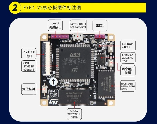
| Model | STM32F767IGT6 core board |
|---|---|
| Size | 55*55MM |
| PCB | 4 layers, black immersion gold |
| CPU | STM32F767IGT6, 176PIN, 1MB FLASH, 256KByte RAM |
| Main frequency | 216M |
| Main frequency | 216M |
| NAND FLASH | 128MB, model: W29NO1GVSIAA, store data |
| Serial FLASH | Capacity 32MB, model: W25Q256, can be used to store fonts and other user data to meet the requirements of large-capacity data storage. |
| SDRAM | 32MB, model: W9825G6KH-6, easily cope with various scenarios of large memory requirements, such as GUI design, algorithm design, big data processing, etc. |
| Download | 1 SWD download port, the debug interface (SWD) of the core board, which can be used for code download and simulation debugging. |
| Key | 1 reset key, 2 user keys |
| Micro USB interface | 1, used for 5V power supply, the USB interface (USB) of the core board, adopts the Micro USB interface, which is common with the mobile phone data line. This interface can be used as a USB SLAVE or as a USB HOST (OTG), as a HOST When using it, an external USB OTG cable is required. At the same time, this interface is also the main power supply port for the core board (when the core board is used alone). |
| LDO chip | 1, voltage conversion chip, realize 5V to 3.3V |
| EEPROM | 1, the core board model is: 24C02, the capacity is 2Kb, that is, 256 bytes. It is used to store some important data that cannot be lost when power off, such as some parameters set by the system/touch screen calibration data, etc. With this, you can easily realize the power-down data storage. |
| LCD interface | 1, using a 40P flip under the FPC, 0.5MM spacing, the data format is RGB888 |
| LED | 1 power LED |
| GPIO | All IOs are led out by BTB interface, and function modules can be connected externally. |
● STM32 development board (STM32F767IGT6) – V2 Baseboard hardware configuration checklist
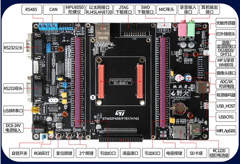
| Model | STM32F429_F767_H743 baseboard (F4/F7/H7 shared baseboard) |
|---|---|
| Size | 200"130.5MM |
| PCB | 2 layers, black gold immersion gold |
| Core board interface | BTB interface, compatible with F429 and F767 and H743 core boards |
| WIFI | Model: AP6818, SDI0 bus interface, the maximum speed can reach 1.5MB/S, realize wireless network function |
| Ethernet | Model: LAN8720, connect the network cable, realize the function of Internet access |
| EEPROM | Can be connected to HCO5 Bluetooth module |
| SD card | It can be expanded to a TF card within 32GB for storage of large files, such as MP3, video, pictures, etc. |
| RTC transposon | 1 CR1220 battery holder, put the button battery, the backup area of STM32 provides energy, and maintains the storage of data in the backup area and the operation of the RTC when the external power supply is cut off. |
| Power Input | Support DC 6-12V, USB 5V input |
| Power Output | LDO: AMS1086-3.3, can output 3.3V |
| MP3 | Model: WM8978, support playback and recording |
| Buzzer | 1 active buzzer, which can realize functions such as alarm prompt, music box, etc. |
| Potentiometer | 1 of 1K precision patch potentiometer can collect the analog voltage of the potentiometer, the WM+RC filter circuit expands the DAO to output the analog signal, and the ADC can collect such as smoke/harmful gas concentration detection |
| Key | 1 reset key, 2 ordinary keys, 1 capacitive key, which can be used for parameter adjustment control, etc., where RST is the reset function |
| LED | 1 RGB LED, 1 Power LED |
| LCD | External 4.3 inch/5 inch/door 7 inch RGB LCD module |
| STM32 LTDC driver, LCD STM32 development board screen does not need its own driver chip | |
| Accelerometer | Accelerometer | Model: MPU6050 six-axis sensor, can be used for four-axis flight control, balance car and other applications |
| Light sensor | Model: GL5516 (5-10) analog output, sensing changes in light, so that it can achieve automatic backlight control similar to mobile phones. |
| Serial port | 1 USB to serial port (CH340), convert USB port to serial port, can realize automatic download function. One 232 DB9 serial port (MAx3232), connected to an external serial port through a standard DB9 connector. Through this interface, we can connect a computer or other device with a serial port to realize serial communication. |
| USB | 1 USB-device and USB-HOST interface, can realize USB communication |
| CAN | 1, model TJA1050, can realize CAN communication and Modbus protocol, etc. |
| 485 | 1, model MAX485, can realize RS485 communication and Modbus protocol, etc. |
| Download | 1 JTAG interface, support DAP/JLINK/ULINK2/ST-LINK/ARM-OB and other emulator download |
| Camera | The OV2640/500W pixel auto-zoom OV5640 camera module can be expanded with 200W pixels, which can realize photography, video monitoring, QR code recognition, etc. |
| Temperature and humidity | External temperature and humidity sensor DHT11 module and DS18B20 can be connected to detect temperature and humidity. |
| Infrared | HS0038 infrared receiver can be connected externally, which can receive infrared signals sent by remote control |
| GPIO | SDIO, a total of 176 pins, external modules, convenient for users to develop other modules |
| SPI 1/2, 2 interfaces, both can be serial peripheral interface, 2 interfaces can make the microcontroller communicate with various peripheral devices in a serial manner to exchange information. Peripherals include Flash RAM, network controller, LCD display driver, A/D converter and MCU, etc. | |
| I2C 1/2, 2 interfaces, both can be used to connect microcontrollers and peripheral devices in serial communication mode | |
| USART 1/2/3, 3 interfaces, all can be used for serial communication, program download, etc. |
● STM32 development board display (STM32F767IGT6) experiment
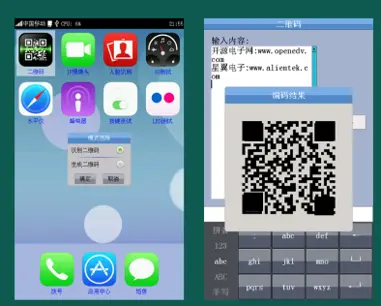
Experiment 1: QR code recognition function
The STM32F767IGT6 development board has an external camera, which supports QR code recognition and QR code generation. QR code recognition supports auto focus. Supports two-dimensional code recognition of UTF8 and GBK encoding methods. It supports barcode recognition of four encoding methods, including CODE128, CODE39, 125 and EAN13. Supports UTF8-OEM conversion output (customers need to provide their own conversion code table).
QR code generation: QR code generation that supports GBK encoding (UTF8 encoding is not supported).
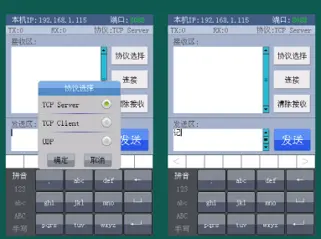
Experiment 2: Network communication test function
On-board 10/100M adaptive Ethernet interface, using IWIP protocol stack, support DHCP, support WEB Server/TCP/UDP and other tests, and provide a test interface similar to the network debugging assistant, the test is very convenient. Just connect a network cable to the router/direct computer to test.
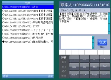
Experiment 3: SMS function
Support SMS reading, SMS reply, incoming SMS buzzer reminder and so on. It needs to be used with GSM/GPRS module.
● STM32 development board (STM32F767IGT6) function application field
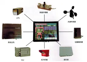
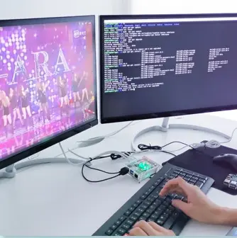
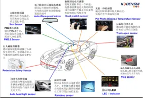
The STM32 development board (STM32F767IGT6) integrates many onboard resources. This stm32 development board kit uses an ARM Cortex M7 core processor. The processor uses a 6-stage pipeline and has a performance of up to 5 CoreMark/MHz. The test data at 200MHz operating frequency is as high as 1000 CoreMarks, far exceeding the previous The highest performance STM32F4 (Cortex M4 core) series, the DSP performance is more than twice that of the STM32F4 series.
At present, the STM32F767IGT6 development board is mainly used for product development in mid-to-high-end industries, and is widely used in industrial control, communication, smart home and other industries, such as industrial control (industrial computer, automatic pipe bending machine, pipe cutting machine, etc.), smart home (refrigerator) , air conditioners, TVs, etc.), automotive electronics (automotive LCD screens, automotive LED lights, automotive intelligent systems, etc.). It is rich in features and has a high price/performance ratio.
● STM32 development board (STM32F767IGT6) FAQ (frequently asked questions)
1: Can't find the USB to serial port?
There may be several reasons for this problem:
1) The development board kit is not powered.
In this case, please check whether the blue power light in the lower right corner of the development board is on, if not, press the power switch. The power indicator must be on for the computer to find the USB to serial port. In addition, this microcontroller development board does not support JLINK power supply, and it is not recommended to use ST LINK to power the development board kit.
2) The wrong USB port is inserted.
To use the USB to serial port, the USB cable must be plugged into the USB_232 interface in the lower left corner of the development board as the picture shows:
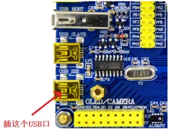
3) The USB driver is not installed.
Please install the CH340G driver. The CH340 driver is located in the CD-ROM: 6, software data\software\CH340 driver (USB serial port driver)_XP_WIN7 shared folder.
2. Comprehensive test experiment, the touch screen is inaccurate/untouchable.
In this case, please calibrate the touch screen.
Calibration method: press and hold KEYO, press reset, release reset (KEYO has been held down during this process), and when it is loaded into Touch Check, the system will enter the touch calibration interface (only for 2.8/3.5 resistive screens). Release the KEYO, then use the pen tip to tap the center of the cross on the screen in turn to complete the calibration. When the calibration is complete, the screen will prompt: Touch Screen Adjust OK, indicating that the calibration is complete.
3. Serial port experiment (experiment 3) no return of data sent
This problem can generally be caused by the following reasons:
1) The serial port is wrong.
Please select the correct serial port (see picture).
2) No new line is sent (or no carriage return is entered).
Friends who use SSCOM and XCOM, note that you must check: Send a new line, as shown in the figure:
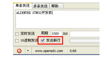
4. Some interfaces cannot be exited during the comprehensive test experiment.
In the comprehensive test experiment, some interfaces, such as drawing, notepad, e-book, etc., do not have a return button on the screen.
At this time, we can press the TPAD touch button in the lower right corner of the microcontroller development board to exit the current interface and return to the main page. interface. as the picture shows:
TPAD is a capacitive touch button, which can be input with a touch of a finger. In the comprehensive experiment, in any interface, you can return by pressing this TPAD button.
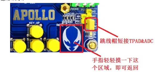
● STM32 development board (STM32F767IGT6) shipping standard list

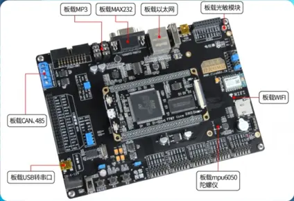
● STM32 development board (STM32F767IGT6) expandable module
